Tuesday, September 30, 2008

Motor Coupler Pt. 2

The last time I was in the machine shop was over a month ago (see August 10th, 2008 post). We had built the collar and key for the motor but were still quite a ways from a completed coupler.

Matt and Mike had some free time Saturday, so we hit the shop! September 27th was actually my birthday so it was a great gift.

First thing Matt and I did (well, really Matt), was weld the key into the collar. We left the collar on the motor while welding to ensure it would still fit later. We've got some great tolerances on the collar - it fits -tight-.

I was nervous about welding the collar while it was on the motor, but after asking a few people it sounded like it would be okay as long as we grounded to the shaft (so the current wouldn't need to find a path through the rest of the motor). Hence, the bolt...


My excitement during the welding process caused me to forget to take pictures, but here's a shot of the completed piece!


Matt just did a few quick spot welds while the collar was on the shaft. The finish welding was done after the collar was removed.

There was some progress on the coupler the previous couple weeks - Matt had 2 flanges created. One for the motor collar and the other for the clutch/transmission collar. Our next step was to attach the motor-side flange onto the motor collar.


A couple tack welds...


And finishing it off...


Matt had an engineered block to check its perpendicularity (wow, my computer says that's a real word!) It was dead on with the tack welds, but shifted a hair in the final weld. Should be good though!

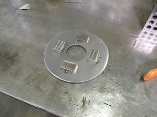
Originally we were planning on drilling holes in the clutch piece to attach it to the transmission-side flange, but we weren't sure how well the clutch would take the drill or the loss of material. In the picture above, you can see the clutch piece next to the motor collar. Instead of drilling, we decided to try machining blocks that would slide into the four holes of the clutch to transfer the torque from the motor.

Mike prepared a length of steel while we were working on the collar. It was time to cut up the steel into 4 blocks. You can see 2 of the cut blocks just above the air nozzle.


This is a pretty sweet machine...


It is refining the rough cuts into exactly the width required for the clutch. Matt operating the machine...


We used a pipe to ensure our clutch was centered on the transmission-side flange. Placing the newly created blocks...


And then tack welded them in place...

My help! Matt and Mike (brothers--obviously). Thanks for the help guys!


Here's the coupler (basically) done. You can see the steel blocks that will grab onto the clutch that will then turn the transmission shaft.


We spent some time trying to decide how to attach the clutch onto the transmission-side flange (and then, how to attach the transmission-side flange to the motor-side flange).

One thought was to not attach the clutch to the flange, but just let it be pushed into place when the motor was connected to the transmission. Unfortunately the transmission shaft is fairly long, and it will be a pain to try and get the shafts short enough for that to work.

Next idea was to drill holes in the 4 slots of the transmission flange where the clutch wasn't covering, and just bolt the transmission flange to the motor flange. Great, but how do you make sure the clutch piece stays on? Well just throw a big washer over the transmission-side flange that grabs the clutch as well! The power is delivered rotationally, so there will be little (if any) force pulling the pieces apart.

Another thought was to drill the holes through the flanges and through the new blocks. The holes through the blocks would be threaded though so just some bolts could hold the two flanges together. Clean solution, but it still has the problem of how to attach the clutch. It could be possible to weld (or bolt/however) strips of steel between the blocks so the clutch couldn't slide off.

We decided on just drilling through with 4 simple holes and using a big washer to hold the clutch on. Not as clean as I'd like, but it should work fine. Matt is going to finish it up at the shop later (hopefully this week!). Barring any major problems, the coupler is basically done!

Now we just need to start that adapter plate... Matt / Mike, you guys free this weekend?

Sunday, September 21, 2008

Video: Temp & Volt Gauge

My new Volt & Temperature gauges in operation!

Temp & Fuel Gauge

The Spitfire only has four gauges - Speedometer, Tachometer, Fuel, and Temperature. The speedometer should work just fine as it is. The tachometer will need some work - I have a dual shaft motor, so I can pick up a tachometer sensor that will attach directly to my motor.

The last two are what I spent my weekend sprucing up...


Since I pulled the radiator out of the car, the existing temperature gauge no longer had anything to read from. I decided to pull out the gauge and figure out how it worked.


The gauge has a +/- for the instrument light and a +/-/load for the measurement. The + connects to the vehicle's + line, the - connects to the vehicle's ground line, and the load connects to the sensor which then connects to the ground. I hooked up some batteries and a resistor to test out the gauge.


I want to use existing gauges as much as possible. Primarily to keep the classic style of the car but also to simplify the conversion as much as possible. The original sensor is long gone (probably in a Spitfire somewhere in California right now), but it turns out it wouldn't work anyways. The factory sensor has only a single wire input at the rear and its threading makes the ground connection.


Great for regular engines, very bad when your sensor is on a 12V line that probably shouldn't be grounded to a 120V motor. Some vehicles use 2 wire sensors that don't ground at the threads.

I searched around the Internet for a while, but I couldn't find a good way to read the motor's temperature. I decided to check out the local Checkers Auto Parts store. Okay, I am not an employee of Checkers nor do have stock in the company, but they've impressed me very much lately. I've been by there several times the past few months working on my car. I tell the guys/gals what I'm trying to do (a few of them recognize me now as the guy converting his car to electric) and ask what they recommend. The employees have all been very knowledgeable - they don't push me into buying something they have in stock - and they've told me on several occasions that I should go to ___ store instead. Excellent service. Okay, so back to the conversion. Checkers carries several types of gauges, including a style that is darn near exactly like the car's original!


There are 2 types of temperature sensors you can get: electrical and mechanical. The electrical is similar to what the car already had. I could pick up a new gauge for $20, get a 2-wire sensor for $20 (so it doesn't ground to the 120V), and then find a way to attach/bolt it onto my motor. The only existing bolt holes on the motor are for mounting around the accessory shaft, and those are smaller than the typical sensor bolt. The mechanical style on the other hand is pretty cool. The gauge has an electrical connection for the instrument lamp but nothing else. There is a long thick tube coming out of the gauge connected to a sensor. The tube is filled with a gas, and when the sensor heats up the gas expands which moves the needle. It doesn't need electricity to operate, so I can watch the motor cool down with the car off. For installation I just need to thermal paste the sensor onto my motor. The biggest downside is if I do use thermal paste I will have to break off and re-glue the sensor whenever I pull the motor out (hopefully rarely). I bought the mechanical version.

The center dash has not only the temperature gauge but also the fuel gauge - another one that is no longer connected to anything. Checkers had a voltage gauge for the 12V system that looked pretty good. Ideally it would be a 120V gauge... Best case I can find an easy way to cut my main battery pack voltage by 1/10 and use this gauge as the overall fuel gauge, worst case it is a reader for my DC-DC converter. Either way it should work out fine.


Before I installed the temperature gauge I (of course) had to test it. I was afraid that the mechanical gauge would have a large delay between when device heats up and when it shows on the gauge. I went over to my oven, turned on one of the burners, and held the sensor a few inches above the flame. The gauge actually responded very well to the temperature change. Even when I shut off the heat it went down reasonably well.

The motor itself has a built-in temperature sensor. The two wires that come out of the side of the motor are normally open, but when the motor heats up to a dangerous level the circuit closes. As I mentioned in my last post, "you can hook up a buzzer or a light or a plastic hand to slap you in the face" to get your attention. I decided to go with a bright red LED and a rather annoying buzzard. Why both? Well not everyone will see the light right away, so a sound warning is good. If there is a buzzard but no associated light then someone driving my car might not know what it is for. Also, some people may go "oh, I've only got a couple miles to go, the motor can make it" and easily ignore the light. Not this buzzard, it's so annoying you -will- pull over and shut the car off so you don't have to hear it anymore.

A quick drill into the wood instrument panel and I had a hole for my light. I'm putting the light on the "hot" side of the temperature gauge so it will be more intuitive as to what it's for.


Since I'm using the mechanical temperature gauge instead of the electrical, I actually have extra wires available to connect my new warning system. Perfect! Wired up and it's done.


The sensor and overheat wires that will connect to the motor...


System off..


System on...


My voltage is showing lower than I'd like - when I test the voltage at the battery is reads a much healthier 12.5. I may find a different location for the voltage to read from, but it does work for now. The overheat light & buzzard work beautifully! I'm going to post a video next of the new gauges operating.

Oh, I also took care of a few other things while the dash was out. I rotated the headlight switch around. Originally it was top down off, toggle the switch down to turn it on. That seemed counterintuitive to me so I just flipped it around. Now you push the top of the button to turn on the lights. I got the CD/Radio working too! The previous owner installed a CD player, but it wasn't connected to any speakers (and for that matter I couldn't find any speakers in the car!). Luckily I had an extra one in the house and had to try it out.


Success! Time to make a Best of the '50s CD. (Yes, I know it is a 1970's car, but music from the 70's is something to be avoided.)

The wife is ready to take it for a spin!


Now I just need to get that motor installed...

Saturday, September 13, 2008

Video: Motor Bench Test

The first trial of my new motor. I was using a (very) dead battery so the test didn't last too long.

Motor Test Stand / Connections

Well, I had my electric motor for over a month and had yet to run it! Curious to see if it worked (and just because I wanted to see it turn), I decided to test it out.

I was tempted to just leave the motor in its styrofoam packaging and connect up the wires, but since I've never messed with a motor of this size (and didn't know exactly how powerful it would react), I decided to build a proper test stand.

I scrounged around my scrap wood and found some nice pieces of 3/8" plywood, about a foot wide and several feet long. I would have preferred 1/2", but since I won't be putting more than 12V through the motor I figured the 3/8" would be sufficient.


I cut 3 vertical support pieces, a front plate, and 2 side supports.


My motor is 6.7" in diameter - the support pieces have round openings 6.75" in diameter. The face plate also has an opening for the shaft to fit through.


I planned on drilling mounting holes in the face plate so the motor wouldn't be able to rotate on the stand; unfortunately I didn't have any bolts that fit in the motor and I couldn't go to the hardware store. Oh well, it's only 12V right? The motor shouldn't torque too much. Right?


One of my friend's car batteries had just died (it was several years old - had a good long life), and when I heard he had to replace it I jumped at the chance of scrounging it up! (Thanks Chris!) I checked it with a multimeter - only 6V for a 12V battery - yeah, it was dead. Another friend had a battery charger he was letting me borrow. (Thanks Luke!) My idea was charge up the battery then immediately do the motor test. It wouldn't last long, but this was more of an exercise in watching it spin than how powerful it could spin.

I charged the battery for a couple hours then decided to give it a try. The battery read just over 12V for the test, but as I held the multimeter on the battery I could watch it slowly drain. Yeah, that thing was dead.


And then connected to the motor...


Success! I was a bit nervous what would happen, but the motor spun right up and purred like a drowsy kitten. Well, for about 15 seconds... My next post will include a video of the motor running, but it really didn't last long.

Oh, and I -finally- found some official drawings / performance pages on my motor. Google long enough and you can find anything!

There are 4 terminals in the motor (labeled S1, S2, A1, and A2) and 2 wires. The ADC L91-4003 is a reversible motor.

According to the official looking specifications:
To run the motor clockwise, you connect S1 to one battery terminal, S2 to A1, and A2 to the other battery terminal.
To run the motor counter-clockwise, you connect S1 to one battery terminal, S2 to A2, and A1 to the other battery terminal.

I also found instructions online concerning WarP motors and how to bench test them. They read (and I quote), "Caution!!!! Sparks can ignite gases emitted from batteries! If a battery is used instead of a charger, the battery must be at least 20 feet away from the motor in a well ventilated area or preferably outside of the building! The cables MUST be connected and disconnected in the order shown!"
Connecting sequence:
1. Connect cable 1 between A2/S2 and cable 2 between S1/- Terminal.
2. Connect cable 3 to the + Terminal. (Connect to the battery before connecting to the motor!)
3. Connect cable 3 to A1.
Disconnecting sequence:
1. Disconnect cable 1 first. (This deactivates the motor.)
2. Disconnect cable 2 and then cable 3 from the power source.

I don't understand why the connecting/disconnecting sequence is so critical, but there are 8 exclamation marks on those instructions so I decided not to argue!

The two smaller wires from the motor are actually an overheat temperature sensor. The wires are normally open, but when the temperature exceeds 120 degrees C, the circuit closes. Apparently you can hook up a buzzer or a light or a plastic hand to slap you in the face when the circuit closes to let you know the motor is melting. At that point you immediately pull over. (Thank the guys at diyelectriccar.com for that info!) I've got some plans for the temperature sensor, but I'll post those updates later!

Sunday, September 7, 2008

12V Wires

Matt has been busy the past few weekends so we haven't been able to work on the motor mount / coupler. While I wait for those parts though, I'm going to continue working on everything else that needs attention on the car. This past weekend, it was redoing all the 12V lines under the hood. They were a mess - wires unbundled, wires bundled by electrical tape, frayed wires, etc... On top of all that, the high-beams on the right side, the right turn signal, and the left parking light didn't work. After a couple quick (1 hour) trips to Radio Shack, I had all the connectors, wires, and sleeves I needed.

Before shot...


After shot...


The old setup didn't allow me to disconnect the hood lights from the car, which was quite a pain when we took off the hood to get easier access to the engine bay. I added some handy snap clips to make life easier later.


Another before shot wire mess...


Nice and pretty...


The horn wasn't hooked up, and I'm not sure which wires it's supposed to use. I've got a few loose purple connectors that look good, but I'll have to play with the multimeter for a while to know for sure. That will have to wait for another weekend though.